SBN3 ,MPP3, DCS Project
Introduction
In the oil and gas industry, industrial installations present inherent risks to personnel, the environment, and physical assets. Mitigating these hazards requires the implementation of robust automated safety systems and strict adherence to regulatory standards. Modernization of these facilities increasingly relies on advanced remote control and supervision architectures, specifically Distributed Control Systems (DCS).
A DCS is an integrated network of hardware and software designed to distribute control functions across an industrial process. This end-of-studies project, conducted during a practical internship at SONATRACH, focuses on the automation and remote supervision of a Depropanizer unit.
my study is structured as follows:
Phase I: An operational analysis of the LPG treatment process, with a specific focus on depropanizer mechanics.
Phase II: An evaluation of the instrumentation and control strategies required for stable operation. This section also details the hardware and software architecture of the YOKOGAWA CENTUM VP DCS.
Phase III: The development of a custom automation solution. This includes a sequential program designed to visualize operations and integrate automated logic for startup, shutdown, and Emergency Shutdown (ESD) protocols.
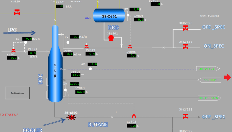
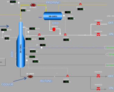
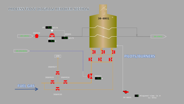
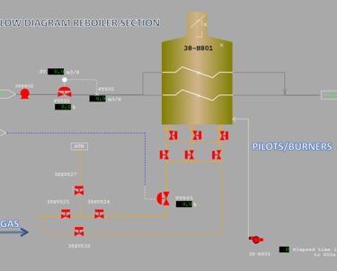
These two images illustrate the HMI (Human-Machine Interface) supervision screens for a Depropanizer Unit and its associated Reboiler Section, typical of an LPG treatment process.
start up depropanizer unit :
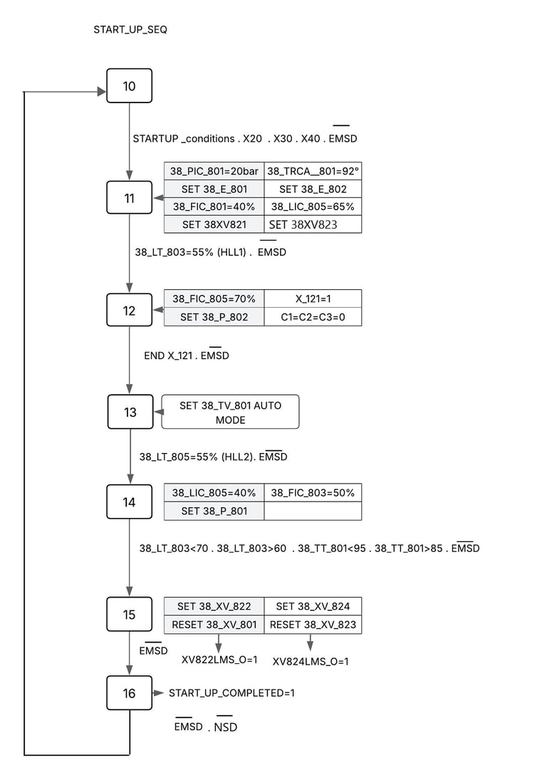
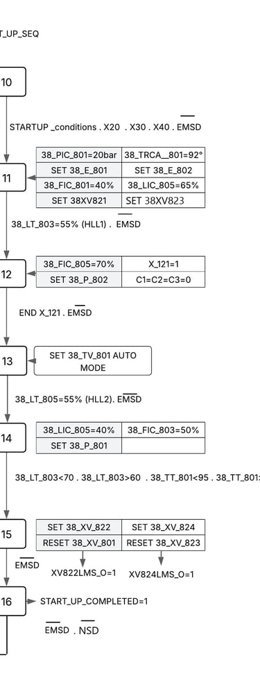
I designed and implemented a multi-stage Grafcet sequence to manage the complex interdependencies between thermal regulation and fluid dynamics.
Interlock-Driven Initialization: The sequence only initiates upon validation of field safety conditions (X20, X30, X40) and the absence of EMSD (Emergency Shutdown) signals.
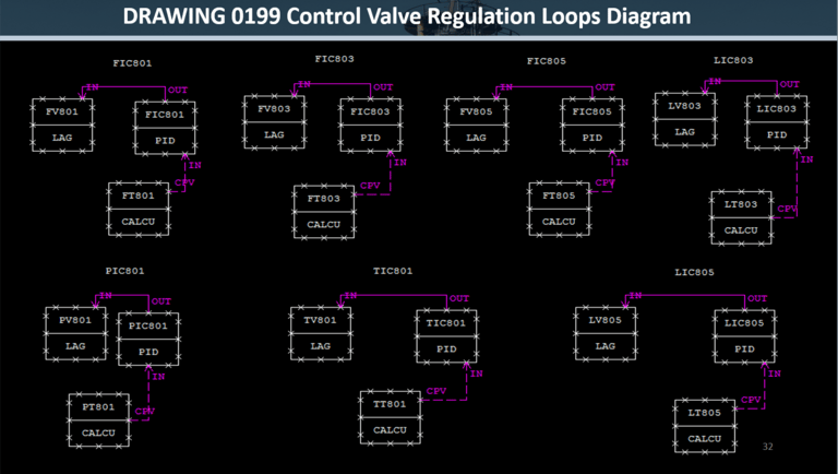
Dynamic Loop Management: Automated the transition of TIC (Temperature Indicating Control) from manual override to Auto Mode once stable reboiler circulation was established.
Synchronized the startup of the Reboiler Pump (P802) and Reflux Pump (P801) based on real-time level triggers (LT803/LT805).
Stability Validation Logic: Integrated a "Condition Gate" (Step 15) that monitors specific temperature windows (85°C < T < 95°C) and levels (60 < L < 70) before transitioning to On-Spec product routing.
Safety Integration: Embedded continuous EMSD/NSD monitoring within every transition, ensuring that any process deviation immediately returns the system to a safe state.
Technical Impact
Reduced Human Error: Eliminated the need for manual valve alignment during the critical heat-up phase.
Operational Consistency: Standardized the startup time and thermal ramp-up, extending equipment life.
Enhanced Safety: Fully integrated the ProSafe-RS safety requirements directly into the control sequence.
Igniting an industrial reboiler is one of the most hazardous operations in a refinery. Unburned fuel accumulation can lead to explosions, while repeated failed ignition attempts require a forced purge of the combustion chamber. The logic must be fail-safe and strictly timed.
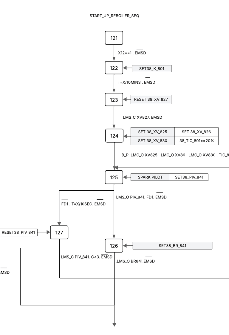
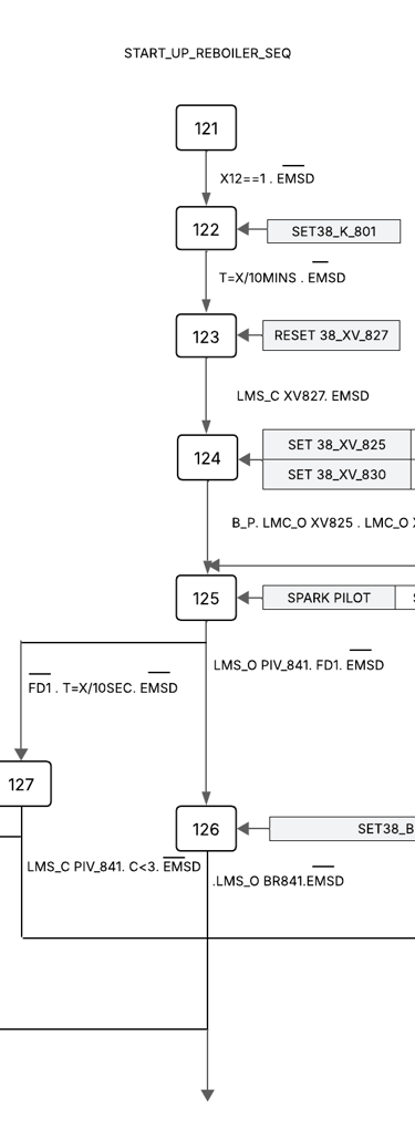
The Engineered Solution (BMS Grafcet)
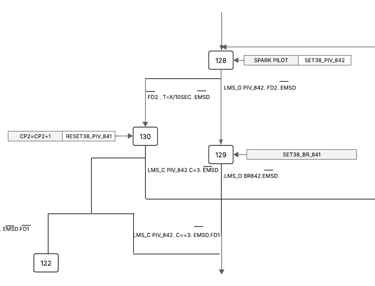
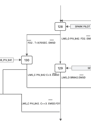
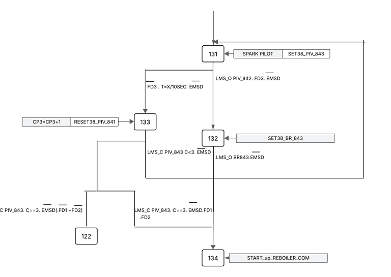
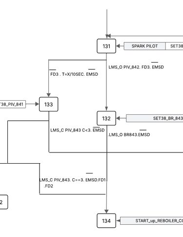
I developed a sequential control architecture to manage the ignition of three pilot/burner sets, integrating rigorous safety checks at every transition.
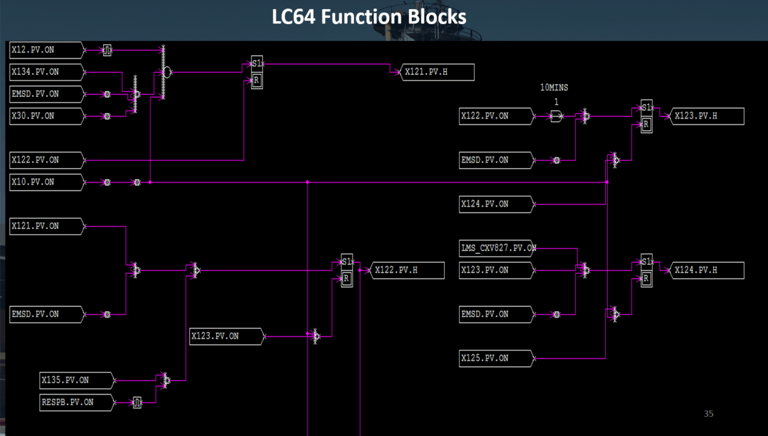
Pre-Ignition Purge & Lineup (Steps 121–124): * Initiates a 10-minute timed purge (38_K_801) to clear residual gases.
Performs automated valve alignment (XV825/826/830) and sets the initial fuel gas pressure via the control valve (TIC_801 at 20%).
Sequential Ignition & Flame Detection: * Manages the "Spark Pilot" phase for each burner unit.
Utilizes Flame Detectors (FD1/FD2/FD3) as mandatory feedback before opening main burner valves (BR841/842/843).
"Three-Strike" Retry Counter (Steps 127, 130, 133): * Engineered a counter system (CP1/CP2/CP3) that allows up to three ignition attempts per burner.
If a flame is not detected within 10 seconds, the system resets the pilot and increments the counter.
Critical Fault Protection: * If the third attempt fails (C=3), the sequence automatically triggers a Hard Lockout, returning the system to Step 122 for a mandatory re-purge, preventing hazardous fuel buildup.
Technical Impact
Safety Assurance: Fully compliant with industrial "Flame Safeguard" standards, ensuring no main fuel is released without a verified pilot flame.
Operational Reliability: Automated retry logic reduces the need for manual intervention during minor ignition delays.
Real-Time Monitoring: Provides the HMI with clear status signals for each stage of the heating process.
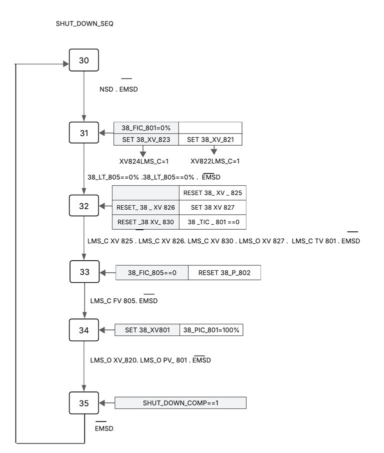
In high-pressure distillation units, a shutdown must be handled with extreme precision. A "Normal Shutdown" focuses on equipment longevity and process stability, while an "Emergency Shutdown (ESD)" focuses on immediate risk mitigation to protect lives and the environment.
The Engineered Solution
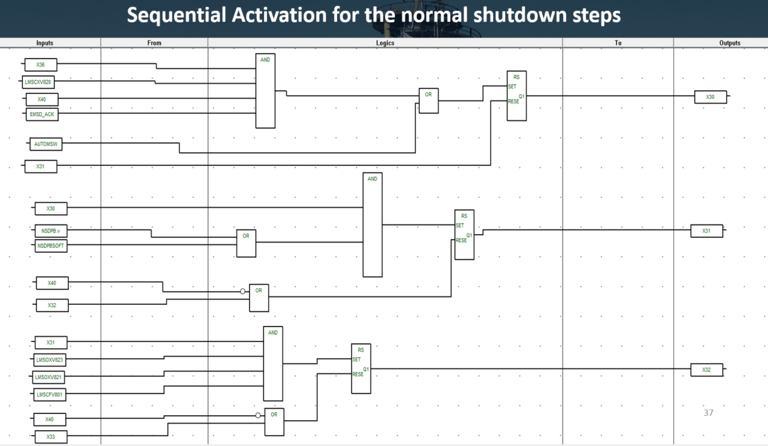
1. Normal Shutdown Sequence (NSD)
I designed a controlled decommissioning logic to bring the unit to a safe "Standby" state without thermal or mechanical shock.
Flow & Product Isolation: Gradually reduces feed rates to 0% and re-routes products to "Off-Spec" storage to prevent contamination.
Thermal De-energization: Systematically shuts down the heating medium, ensuring the reboiler pump (P802) continues circulating until safe temperatures are reached.
Venting & Pressure Management: Opens atmospheric vents and sets pressure controllers to safe limits to equalize the system.
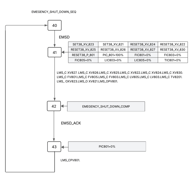
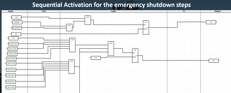
2. Emergency Shutdown Sequence (ESD)
This is a high-priority, "Fail-Safe" logic triggered by critical process deviations (EMSD).
Instantaneous Isolation: Simultaneously closes all inlet valves (XV series) and cuts power to process pumps (P801) within milliseconds.
Energy Blockage: Immediately isolates the fuel gas system (Burner/Pilot) to remove the heat source from the pressurized vessel.
Verification & Acknowledgment: The logic remains in a "Lockout" state (Step 42) until the field operators manually acknowledge the alarm (EMSD_ACK), ensuring the cause of the trip is investigated before any reset is possible.
Technical Impact
Fail-Safe Reliability: The ESD logic is designed to prioritize safety over production, ensuring a "closed-loop" safety state.
Asset Protection: The NSD logic prevents common issues like "vacuum collapse" or "column flooding" during routine maintenance stops.
Regulatory Compliance: Meets the stringent safety requirements common in SONATRACH and international Oil & Gas standards
Systems Engineering is 10% coding and 90% understanding architecture. 🏗️
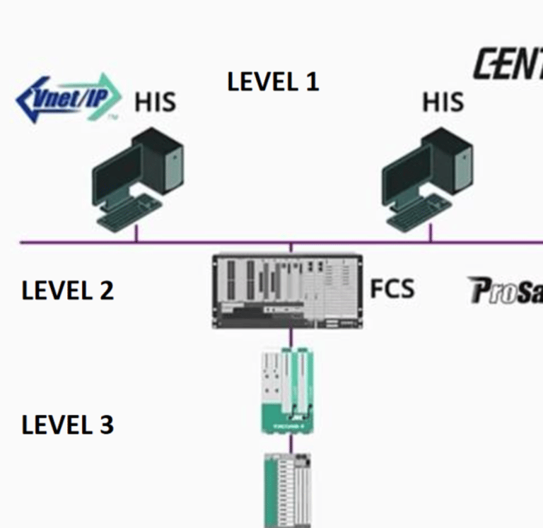
Before diving into the complex logic of Yokogawa Centum VP, you have to master the hardware fundamentals. In the first installment of my new DCS video series, I break down the Integrated Control and Safety System (ICSS) architecture.
We explore:
🔹 The 4-level hierarchy (Field to Supervisory).
🔹 How Vnet/IP ensures high-speed, reliable data flow.
🔹 The critical integration between Centum VP and ProSafe-RS.
System Implementation: Yokogawa CENTUM VP & ProSafe-RS
To bring the Depropanizer automation to life, I executed a dual-platform implementation, separating Process Control from Safety Instrumented Functions (SIF) to ensure maximum reliability and regulatory compliance.
Phase 1: Process Control Station (FCS)
Environment: CENTUM VP – System View
In this phase, I configured the "Brain" of the plant’s daily operations. My work focused on creating a seamless interface between field data and operator control.
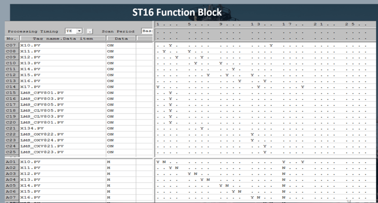
Database Configuration: Defined all I/O modules, Tag Names, and Range Scales within the System View environment.
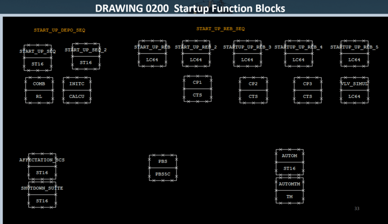
Control Logic (FCS): Translated the Normal Startup and Shutdown Grafcets into Control Drawings (DR). This included:
Regulatory Control: Tuning PID loops for temperature and pressure stability.
Sequence Tables: Implementing the step-by-step logic for pump synchronization and valve lineups.
HMI Development: Designed the high-performance Graphic Windows (as shown in my process flow diagrams) to give operators real-time visibility into the Depropanizer's health.
Phase 2: Safety Control Station (SCS)
Environment: ProSafe-RS – Workbench
Safety is non-negotiable in Oil & Gas. I implemented the Emergency Shutdown (ESD) and Burner Management System (BMS) within the dedicated safety environment to ensure they remain independent of the main process control.
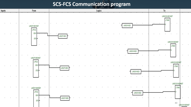
Safety Logic (SCS): Using the ProSafe-RS Workbench, I programmed the critical ESD sequences using Function Block Diagrams (FBD) and specialized safety logic.
SIL Compliance: Ensured that all safety loops were designed to meet the required Safety Integrity Level (SIL) for high-risk furnace and pressure vessel operations.
Integrated Monitoring: Configured the communication link between the SCS and FCS, allowing safety alarms to be visualized on the main CENTUM VP operator stations without compromising the safety loop's independence.

Graphical Simulation of a Depropanizer Unit
Phase 1: Initialization & Global HMI Overview (00:00 – 00:30)
The Interface: The simulation opens on the primary HMI Supervision screen, displaying the 38-D801 Depropanizer Unit and its interconnected reboiler loop.
Logic Execution: Upon triggering the "Auto Start" sequence, the integrated Grafcet Simulation begins its step-by-step validation.
Objective: To automatically verify all field conditions and interlocks, ensuring the plant is in a "Ready-to-Start" state before any fluid movement occurs.
Phase 2: Reboiler Thermal Startup (00:30 – 01:02)
Thermal Sync: Once the column reaches the calibrated hydrostatic level, the sequence initiates the 38-H801 Reboiler startup.
Burner Management (BMS): The simulation visualizes the automated purge cycle, pilot ignition, and main burner ramp-up.
Objective: To establish a stable thermal gradient, which is critical for high-purity propane and butane separation.
Phase 3: Steady-State Stabilization & Product Routing (01:02 – 01:43)
Operational Transition: As the unit reaches thermal equilibrium, the simulation shows the transition of regulatory PID loops from "Manual" to "Auto."
Final Alignment: The logic confirms process stability, automatically opening the "On-Spec" valves and bringing the unit into full service.
Objective: Achieving a smooth, risk-free transition from startup to continuous production.
Phase 4: Normal vs. Emergency Shutdown (01:43 – 02:35)
Controlled Decommissioning (NSD): This sequence demonstrates a step-by-step reduction of feed and heat, prioritizing equipment longevity and preventing thermal shock.
Safety Instrumented System (ESD): In contrast, the ProSafe-RS safety logic demonstrates an instantaneous "Fail-Safe" response. Unlike the sequential normal shutdown, the ESD triggers a simultaneous isolation of all energy sources and process inlets.
Objective: To prove the system’s ability to return the unit to a zero-energy state instantly during a critical process deviation.